| Home | AmMin | GMR | RiMG | Collectors Corner | Directory | Short Courses | |
|
|
|||||||

|
|
Volume 16, pages 55-70, 1931
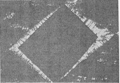
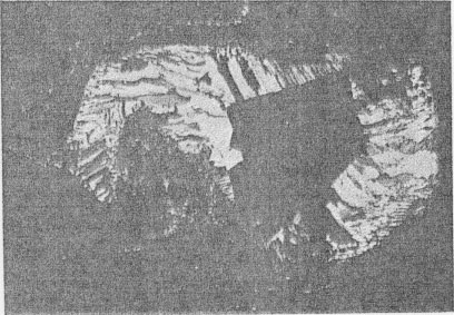
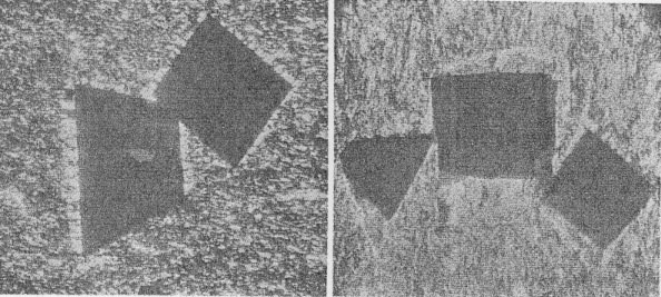
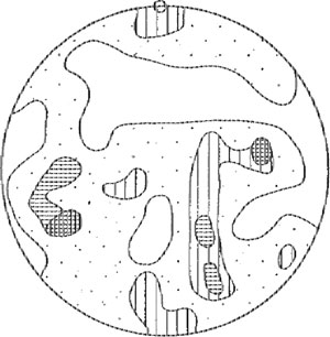
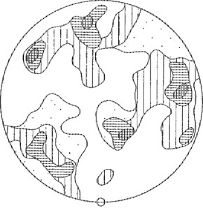
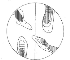
"PRESSURE-SHADOWS" AND THE MEASUREMENT OF THE ORIENTATION OF MINERALS IN ROCKS ADOLF PABST, University of California. INTRODUCTION "Pressure-shadows" is the name sometimes applied to the fringes or halos differing from the groundmass that often accompany porphyroblasts in schistose rocks. Excellent examples of pressure-shadows were found with the pyrite porphyroblasts in the Calaveras formation and associated rocks at Carson Hill in the Mother Lode region of California. The pressure-shadows are always widest in the direction of "Streckung"1 and are sometimes notably elongated. In the larger shadows it is easily seen with the unaided eye that they are filled with fibrous quartz. This occurrence seemed to offer an excellent opportunity for the study of the orientation of the quartz and of the factors affecting it. To this end the universal stage was used. In the following the material will be described, the method of study outlined, and the results of the measurements presented in graphical. form. Grateful acknowledgment is made to the Research Board of the University of California for a grant which made possible the present study. PREVIOUS OBSERVATIONS Knopf2 has described "pressure-shadows" associated with ankerite and pyrite in the rocks of the Mother Lode region. He says in part, "Associated with some of the larger pyrite crystals is the quartz with the curious structure that causes it to be termed feather quartz." The microphotographs, Plates 8A and 8B, in the paper cited, show that the features referred to are the same as those here to be considered. Moss3 has described in detail the geology of the area in which the materials for the present study were collected. He also observed the "pressure-shadows," but referred to them as "Streckungshoefe," which he described both in the "Melones slate" (a member of the Calaveras formation) and in altered wall rocks. FIELD OBSERVATIONS Although the statements of Knopf indicate that similar materials are to be found elsewhere along the Mother Lode, the writer's observations are restricted to an area within several miles radius of Carson Hill. The rocks are largely those of the Calaveras formation and amphibolite schist.4 The Calaveras formation includes a great variety of metamorphosed rocks. For the most part they are slaty and in parts they are highly graphitic. The rock cleavage strikes uniformly NW and dips steeply to the NE. Even those rocks which did not lend themselves to the development of slates, such as conglomerates, show a marked schistosity and stretching. In the vicinity of the quartz veins and ore bodies, which in the main follow the regional strike, large masses occur, of altered rocks rich in carbonates and talc. Pyrite, commonly associated with some of the gold ores, occurs sporadically in all of these rocks for several miles on either side of the highly mineralized belt. Sometimes the pyrite is fairly evenly distributed through the rock, or it may be in nests or stringers that may show a relation to a crack or a quartz veinlet and may parallel or transect the schistosity. Often the pyrite can be seen to be restricted to a zone in the rock from a few inches to several yards in width. The pyrite varies from the most minute grains to cubes 4 or 5 mm. on an edge. The dominant form is the cube. The only other form observed, the pyritohedron, is quite subordinate. The usual striations are invariably present. No regularity in the orientation of the pyrite with respect to structures in the enclosing rock could be found. Occasional crystals are elongated or shortened parallel to one cube edge. Several large slabs of soft slate, from which the hard, perfectly coherent, limonite pseudomorphs after the pyrite could be easily removed, were brought into the laboratory. The number of cubes departing sufficiently from the ideal shape that they could be recognized without measurement was less than 1%. This left such a small number of distorted crystals that it seemed hopeless to try to find any regularity in their orientation. In the field pressure-shadows are often seen beside the pyrite, the limonite pseudomorphs, or the cavities left by the removal of these minerals. They are most easily seen where they are associated with the larger pyrite crystals and where they occur in the dark even-grained graphitic slates. It is also in these cases that they possess the greatest constancy of structure and composition, as will be described later. By megascopic observation only the larger shadows, which may equal or exceed the pyrite crystals in size, are discernible. These again are restricted to certain zones or patches within the areas bearing pyrite crystals. No obvious relation was found in the field between the distribution or frequency of occurrence of the pressure shadows and features of the enclosing rocks, but the microscopic study yielded some suggestions. Quartz is the only constituent of the shadows that can be surely recognized in the field. Nevertheless, the cellular character of the shadows in some places and their entire removal in others indicate the former presence of other minerals. MICROSCOPIC DESCRIPTION Specimens of various rock types bearing pyrite porphyroblasts from a dozen different points near Carson Hill were studied microscopically. Pressure shadows were found in all, though the character of these varies greatly with the size of the pyrite crystals and the nature of the enclosing rock. There is great constancy in the character of the shadows from any one locality. Where the average size of the shadows is small they may be entirely lacking from some of the pyrite crystals. The pressure shadows are invariably extended in the direction of the schistosity. They appear on one or both ends of the pyrite crystals and not infrequently narrow fringes entirely surround the pyrite. The shape of the shadows is largely dependent upon the orientation of the porphyroblasts with respect to the schistosity. If a cube face is perpendicular to the schistosity the shadows are generally rectangular in cross-section. Where the cube faces are oblique to the schistosity the shadows are often wedge-shaped, as shown in Fig. 1. For the most part the shadows are exceedingly regular in structure and are bounded by plane surfaces. Such shadows though they vary in width, are rarely if ever wider than the pyrite crystals to which they are attached and mostly they are much narrower. From a single locality, the dump of the Tulloch Mine, specimens of shadows of an entirely different sort were obtained. Here the rock is a crumbling graphitic slate. The shadows are usually very much larger than the pyrite about which they occur. They are irregular in shape, heterogeneous in structure and composition and much elongated in the direction of schistosity as is shown in Fig. 2. Some of these, at least, seem to have formed while the matrix was undergoing movement so that several stages in their formation may be recognized. They will not be further considered here as they seem to be dependent on local conditions and to differ sharply from the more typical shadows.
The minerals of the pressure-shadows, in order of frequency of occurrence are: quartz, chlorite (probably penninite), carbonates (calcite or ankerite) and sericite (talc?). A particular shadow may contain any one or any group of these.
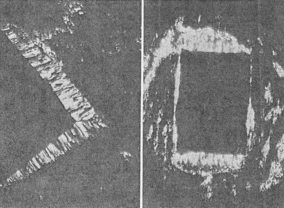
The shadows are best developed in the smooth graphitic slates of the Calaveras formation. They consist of feather quartz with minor amounts of the other constituents as shown in Figs. 1, 5, and 6. They are entirely free from any remnants of the matrix. The quartz is invariably oriented with the axes of elongation of the grains normal to the pyrite face on which the shadow occurs, even in those parts where the feather quartz is not in contact with the pyrite. Most frequently the minor minerals lie in the outer part of the shadow. If granular quartz is present it likewise tends to lie at the outer edge of the shadow giving way to feather quartz near the pyrite. A few shadows contain coarser and finer feather quartz. In these cases the coarser quartz is usually toward the inside. Exceptions to these more common arrangements of the constituents in the shadows are rare. In some other rocks, as the quartz-carbonate or talc-carbonate rocks in the highly mineralized zones, chlorite, sericite or carbonates may be the chief minerals in the shadows, sometimes with narrow fringes of feather quartz as shown in Fig. 4. In the case of small pyrite crystals a shadow may consist of a single crystal of sericite or chlorite with the basal plane parallel to the pyrite face.
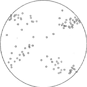
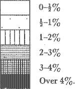
METHOD OF MEASUREMENT The orientation of the long dimensions of the quartz grains normal to the controlling pyrite face is so striking and so constant that it hardly requires measurement. The question arises whether there is any constant relation between the elongation of the grains and the crystal lattice. To answer this it is necessary to obtain data as to the orientation of some crystallographical direction of the quartz with respect to some system of reference. These data are obtainable by measurement of the orientation of the optical ellipsoid under the microscope. This may be carried out by measurement of the azimuths of the projections of the optic axes for uniaxial minerals and may be amplified by repetition on thin sections cut in three planes at right angles.5 The use of the universal stage permits a more complete measurement and seems especially adapted to the present case. The study of the orientation of minerals in rocks has been carried on most diligently for sometime by Sander and Schmidt and their students and reference should be made to their writings for an exhaustive discussion of the many problems involved. More recently Schmidt6 has introduced the method of the universal stage to these studies and has given a convenient method of representing the results. In this discussion the method and the conventions of Professor Schmidt will be followed closely and reference can be made to the paper cited for points not covered here. The work was done with a Leitz Universal Stage mounted on a Leitz petrographic microscope fitted with an arresting clamp under the microscope stage. Because of the fine grain of some of the material measured a 24 mm. microsummar objective was used, since this gives the maximum magnification combined with sufficient clearance above the stage. It was only possible to work with bright illumination since it was necessary to stop down both the objective and sub-stage diaphragms to small openings. In addition a guiding-sledge (after W. Schmidt as furnished by E. Leitz, Wetzlar) was used and attached to the mounting of the upper hemisphere of the universal stage. This attachment allows the thin section to be moved between the hemispheres without loss of orientation and is essential to all such measurements as those here reported. Under the universal stage it is easy to establish the direction of the optic axis of a uniaxial mineral. If the horizontal projection of the optic axis is brought to coincidence with the direction of the A4 axis7 by turning on the A1 axis and the section inclined by rotating on the A4 axis, the mineral will (unless its optic axis lies in the plane of the section) be turned out of the extinction position. If the section is now tilted by rotation of the A2 axis to re-establish extinction and A4 turned back to zero, one of two positions will have been reached; the optic axis now coincides with either A4 (equatorial position) or A5 (polar position). This is determined by rotating on A5. If the mineral is in the polar position it remains at extinction; if it is in the equatorial position it shows maximum interference colors. Those grains whose optic axes lie near 45° to the plane of the section may be read from both positions.8 Thus are obtained two values for each grain examined, the readings on A 1 and A2 for one or another of the two positions. These values may be thought of as defining points on a sphere and as each defines two points at opposite ends of a diameter it is necessary to make an arbitrary decision as to which is to be used. Following Schmidt we will use the lower hemisphere.This hemisphere is now projected onto the equatorial plane by an equal-area projection, necessitated by the statistical purpose and differing from a stereographic projection in that polar distances are plotted after the equation, r=2a sin φ/2, from the center. In practice the readings are plotted directly on the projection. The readings on A 1 give the azimuths. For equatorial positions the readings on A2 are plotted in from the circumference and for polar positions they are plotted out from the center, care being taken in every case to note whether the stage was tilted to the right or to the left. By thus plotting all observations a series of points is obtained as shown in Fig. 9 which show the distribution of the c axes of the measured grains.9It has been customary in the work of Schmidt and others that this projection be subjected to further graphical treatment. The percentage of the total number of plotted points falling within 1% of the area of the projection is measured by running a square having 1% of the area of the projection over it and counting the number of points in the square which, divided by the number of grains measured gives the percentage density of distribution over the projection. 10 Contour lines may then be drawn according to some arbitrary scheme and the areas shaded between the several contours. In this way Fig. 10 was obtained from Fig. 9.The accuracy of such a representation depends upon the degree of orientation of the crystals and upon the number measured. Where the orientation is complex or poor the measurement of several hundred is desirable. It also must be emphasized that lack of orientation combined with a limited number of measurements unavoidably leads to the appearance of a patchy distribution. Very many measurements would be required to give a uniform distribution of points over the entire projection. A limit to the shadows or the grains that can be used for orientation measurements is set by the size of the grains. With favorable orientation of the boundaries and of c axes the smallest grains distinguishable by the observer are susceptible to measurement, but it is always necessary that in the final position of the stage the grain under observation shall show a visible breadth that does not overlap with other grains vertically, otherwise the proper extinction position cannot be recognized. In general the diameter of a grain in random attitude and with boundaries normal to the plane of the section must be more than double the thickness of the section. Other data may be entered in the projection to show the system of reference. If oriented material has been collected and due care taken in the marking of specimens, cutting and mounting of sections, measuring and recording, it will be possible to show north, east, direction of schistosity or any other known direction in the orientation diagram. This is useful in the application of such measurements to structural problems, especially in schistose rocks. RESULTS OF THE MEASUREMENTS The material collected for the present study was in part oriented in the field, but since the attitude of the schistosity is uniform throughout and since the purpose of the work has no connection with structural relations the field orientation need not be considered in the diagrams here presented. The largest number of measurable quartz grains found in a single shadow was 81. This number is smaller than would have been desirable. The orientation diagram obtained for this shadow is shown in Fig. 7. The patchy pattern does not disclose any simple orientation and may be the result of a limited number of measurements in an unoriented aggregate. All other single shadows measured show a similar lack of orientation but lend themselves even less to statistical treatment because of the smaller number of grains.
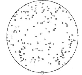
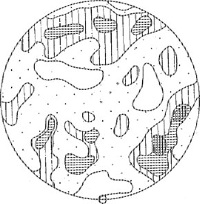
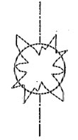
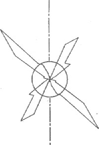
To obtain a larger number of points on one diagram all the measurements from the shadows in one thin section were combined for the orientation diagram shown in Fig. 8. The plane of the projection is the plane of rock-cleavage and the direction of the Streckung is, of course, the same for all the shadows. Again the pattern is a patchy one and shows no dependence on the direction of the Streckung. Fischer 11 has combined similar measurements from a large number of shadows by referring all the measurements to the faces of the porphyroblasts. The same procedure has been followed in making Figs. 9, 10 and 11. Fig. 9 shows the poles of all the quartz grains measured in seven shadows attached to pyrite faces of accurately known attitude so that they could be combined by reorienting the original projections to bring the pyrite faces into coincidence. Fig. 10 shows the orientation diagram for the same material. It shows the same patchy pattern as Figs. 7 and 8. For those who are more accustomed to the older type of orientation diagram the azimuths alone from the measurements for Fig. 9 are plotted in Fig. 11. This gives the sort of a diagram that would have been obtained had the projections of the optic axes been measured without the use of the universal stage.12All these orientation diagrams show the irregular pattern which Schmidt 13 says is typical of unoriented or poorly oriented material. This lack of orientation is most' surprising in view of the constancy in character of the feather quartz. It is also in conflict with the conclusion drawn by Fischer that the c axes of the quartz grains tend to be oriented normal to the controlling crystal face, though he states that this orientation is rather imperfect.14 If the orientation of the quartz in the present case were as he suggests there should be maxima at the top (and bottom) and minima bands across the center in Figs. 7 and 10. Certainly no such arrangement can be seen.The suspicion arises that the comparatively small number of measurements is insufficient to show the arrangement. 15 To check this 100 quartz grains were measured in a thin section of "meso alkali-feldspar gneiss," Chemnitz, Saxony, from the "Grubenmann collection" of the University of California. The results are shown in Figs. 12, 13 and 14, which should be compared with Figs. 9, 10 and 11. It is seen that in the case of good orientation the measurement of even 100 grains is ample to bring out the arrangement very clearly in a diagram. Moreover the minima are entirely clear and after the measurement of but 25 grains the result was easily to be foreseen. In addition a comparison of Figs. 13 and 14 shows the superiority of measurement on the universal stage and representation in the equal area projection over the old methods. Two continuous diagonal bands or just two patches, say at the upper right and lower right sides of the projection in Fig. 13, would have the same appearance as Fig. 14 in the purely azimuthal projection.
Certain statements as to the orientation of the quartz in these pressure shadows now seem justified: 1. Where definite feather quartz is developed the long axes of the grains are at right angles to the controlling pyrite face whatever its attitude with respect to the schistosity of the enclosing rock. This is in harmony with the observations of others. 2. The measurements here reported do not indicate that there is a tendency for any crystallographic direction of the quartz to parallel the elongation of the grains. This conclusion conflicts with that of Fischer who thought he recognized a tendency for the c axes of the quartz to assume a position normal to the controlling crystal face . 16 Still the diagrams he presents show no pronounced maxima and it seems that they may be merely the equivalents of such patchy patterns as are shown in Figs. 7 and 10. In any event it is certain that the orientation of the quartz crystals is very poor at best. It is, for instance, not nearly so good as the orientation of the constituents in a granitic rock showing only a very moderate flow structure.17In a very few cases carbonates were found filling a shadow with elongated grains similar to feather quartz. They show the same lack of orientation. Enough measurements were not carried out to warrant their publication. ORIGIN OF THE FEATHER QUARTZ Before the origin of the pressure-shadows can be taken up it is necessary to consider the relation of the pyrite crystals to the slate. Knopf says, 18 "Metasomatic pyrite is common in sharp crystals, which invariably transect the cleavage of the slate - a feature that points to the relatively late introduction of the pyrite, after the flowage of the slate had ceased." He makes no statement as to the origin of the pressure-shadows filled with feather quartz, but, as they are quite different from the pressure-shadows formed by replacement in association with "augen" of carbonates, it seems that they require a different explanation.The lack of inclusions of matrix in the pressure-shadows, their sharp boundaries, their extension in the direction of the Streckung, and the evident movement of the enclosing slate about them in some cases lends plausibility to the assumption that they are the result of extension in the slate in the plane of schistosity which tended to pull the matrix from the sides of the pyrite porphyroblasts, the potential opening being filled continuously with quartz. Professor Mügge has given a description of similar material and has elucidated the formation of such shadows (Streckungshöfe) with the aid of schematic drawings. 19 The filling of such potential openings with new mineral matter is easily explained by Riecke's principle.20Mügge also gives an explanation of the origin of feather quartz which fits the results here obtained. 21 If quartz seeds begin to grow at the boundary of the slate which tends to be pulled away from the porphyroblast, they will grow in all directions until they hinder each other laterally. Then they will continue to grow inwards into the potential opening at rates depending on the orientation of the several grains. Mügge distinguishes three cases:1. If the rate at which the space is being opened 22 is greater than the maximum growth rate of the quartz grains an empty space will form in front of them. Then new nuclei may start in this space or, failing this, the grains with axes of most rapid growth normal to the surface of the aggregate will suppress the other grains. A fibrous aggregate normal to the surface from which growth occurs and with a measure of crystallographical orientation would result.2. If the rate of opening of the crevice is between the maximum and minimum growth rates of the grains, the slow grains are again suppressed but the faster grains remain in contact with the opposite surface and hindering each other laterally will form a fibrous aggregate normal to the opposite surface and with some measure of crystallographical orientation. 3. If the rate of opening of the crevice is less than the minimum growth rate of the grains, all remain in contact with the opposite side and have an equal chance. Then a fibrous aggregate results with the fibres normal to the opposite side but without crystallographical orientation. If such a scheme is acceptable it appears that the third case is realized in the material examined. NOTES 1 The German word Streckung is used to designate the linear element in the plane of schistosity. The writer would be thankful for the suggestion of a suitable English word. 2 Knopf, A., The Mother Lode System of California, U. S. Geol. Surv., Prof. Paper 157, pp. 41-42, 1929. 3 Moss, F. A., The Geology of the Mother Lode in the Vicinity of Carson Hill, Calaveras County, California, Thesis, University of California, 1927; also Moss, F. A., The Geology of Carson Hill, Eng. and Mining Journal, vol. 124, pp. 1010-1012, 1927. 4 For a geological map of the Mother Lode belt, see A. Knopf, op. cit. or Folio, 63, Geol. Atlas of the U. S. 5 G. Fischer, Gefuegeregelung and Granittektonik, Neues Jahrb., Beil. Band, Abt. B, vol. 54, pp. 95-114,1926. 6 Schmidt, W., Gefuegestatistik, Tschermak's Milt., vol. 38, pp. 392-423, 1925. 7 For a general description of the use of the universal stage see M. Berek, Mikroskopische Mineralbestimmung mit Hilfe der Universaldrehtischmethoden, Berlin, 1924; for a brief account A. N. Winchell, Elements of Optical Mineralogy, Part I, 3rd. Ed., 1928. Of the three cases there mentioned on page 225, only the first two are possible in uniaxial minerals, the second being the general case. 8 Note that A3 is not used in dealing with uniaxial minerals and is conveniently kept clamped at 270° during these measurements. 9 It should be noted that this still allows an infinite number of orientations to each grain as the several directions normal to the optic axis of a uniaxial mineral cannot be distinguished by optical means. In the case of biaxial minerals each grain must be represented by two points corresponding to some chosen two axes of the triaxial ellipsoid. This completely defines the orientation of the crystal lattice if the optical orientation be known and constant. The writer hopes soon to present examples of the measurement of biaxial minerals. 10 A transparent square grid may also be used for this purpose.. Where the number of points is small it is best to count them within some larger unit, say 2 or 4 per cent of the area. 11 Op. cit., p. 112. Fischer did not use the universal stage. 12 Fig. 11 is comparable to Fischer's Fig. 30. 13 See the similar patterns in the paper cited. 14 See especially Fischer's Fig. 31 in the paper cited. 15 Though Schmidt has published orientation diagrams based on less than 50 grains. See W. Schmidt, Zur Regelung zweiaxiger Mineralien in kristallinen Schiefern, Neues Jahrb., Beilb. 57 A, pp. 203-222, 1928. 16 In Fischer's case magnetite crystals. Op. cit., p. 111. 17 Compare, for example, A. Pabst, Observations on Inclusions in the Granitic Rocks of the Sierra Nevada, Univ. Calif. Publ. Bull., Dept. Geol., vol. 17, pp. 325386, 1928, Fig.7. 18 Op. cit., p. 42. 19 Mügge, O., Ueber die Entstehung faseriger Minerale and ihrer Aggregationsformen, Neues Jahrb., Beilb. 58 A, pp. 303-348,1928. 20 Schwinner, R., Kristallisation unter gerichtetem Druck, Tschermak's Mitt., vol. 37, pp. 219-235, 1926. S. points out that Riecke's principle is often misinterpreted but that it does state that the solubility of an unstressed crystal is lower than that of a stressed crystal, other things being equal. This allows the migration of matter in rocks under stress to points sheltered from stress as, for instance, pressure-shadows. 21 Op. cit., pp. 308-315. 22 That component of the rate of movement of the slate normal to the pyrite face in question may be taken as the rate of opening.
| ||||||||||||