| Home | AmMin | GMR | RiMG | Collectors Corner | Directory | Short Courses | |
|
|
|||||||

|
|
Volume 57, pages 1272-1293, 1972 GROWTH MECHANISMS AND POLYTYPISM IN SYNTHETIC HYDROXYL-BEARING PHLOGOPITE A. BARONNET, Laboratoire de Minéralogie et Cristallographie et Laboratoire des Mécanismes de la Croissance Cristalline associée au C. N. R. S., Université de Provence, Saint Jérome, 13 Marseille 13ème, France ABSTRACT Self-nucleated and hydrothermally grown minute phlogopite crystal populations have been studied by electron microscope. Growth by Frank's spiral mechanism is observed after an initial growth by a layer mechanism. Different types of spirals and their interactions have been analyzed and correlated with polytypism in this mineral. Two different basic structures of layer-growth 1M[0] and 1Mrn(120) have been directly identified. INTRODUCTION In order to gain a better understanding of the correlation between polytypism and growth mechanisms of micas, a statistical study of crystallites, as suggested by Smith and Yoder (1956), may give more precise information than the previous studies of Amelinckx (1952a), Amelinckx and Dekeyser (1953), Sunagawa (1964), and Kretz (1966) these authors were working on well-developed natural specimens grown at low supersaturations and showing only the late-growth features on (001) faces. The more interesting observable phenomena connecting growth mechanisms with polytypism are encountered in the first stages of crystal growth. With that in mind, we have performed a careful microtopographic study on crystallite populations of controlled chemical composition and growth conditions. In order to describe the time evolution of the surface structure from a single specimen, we have followed this evolution on a series of crystallite populations with increasing run durations, rapidly quenched from hydrothermal growth experiments. Later on we will be able to define a "representative crystal" from each population showing the statistically dominant growth features and consider the implications of its microtopographic evolution on the crystal structure. This study was carried on hydroxyl-bearing phlogopite, a mineral of common occurrence in ultrabasic igneous rocks and in marbles. METHODS OF INVESTIGATION Synthesis and Growth Conditions Phlogopite synthesis and growth are carried out in sealed gold tubes held in "cold seal" pressure vessels (Tuttle, 1949). Pressure is applied by an isostatic pump and the desired temperature is obtained by external heating of the vessel. Pressure rise with time in the gold tube during temperature rise of the vessel is achieved in such a way that, in all the runs, the internal volume expansion of the tube is always reproducible. This careful regulation is necessary to obtain good reproducibility of the results between different runs at identical final P and T. The initial material is a stoechiometric mixture of K, Al, and Mg nitrates mixed with high purity amorphous silica. The mixture is heated up to 500°C during two hours to remove most of the NO2 (Roy, 1956). The resulting powder is ground and used as the starting charge. All the crystalline populations are grown under the following conditions: amount of starting charge, 25 mg; weight of doubly distilled water, 100 mg; temperature 600 ± 2°C; pressure 1020 ± 34 bars; axial thermal gradient along the gold tube 2-3°C/cm; gold tube length, 30 mm. The only variable is the run duration t; the origin of time t0 is taken at the moment when P and T in the vessel reached stationary values, i.e., 90 minutes after the vessel is inserted in the furnace. The chosen t values are: t1 = 10 minutes; t2 = 1 hour; t3 = 3 days; t4 = 15 days; t5 = 30 days. Methods Employed for the Microtopographic Study At the end of a run, the crystalline power is spread on thin glass microscope slides and then submitted to platinum/carbon shadowing, gold flash evaporation and impurity decoration. Platinum/carbon shadowing. When the best contrast conditions are realized, this method is capable of a resolution of about 10 A, i.e., the height of a elementary mica layer. Gold flash decoration. This technique (Bassett, 1958; Sella, Conjeaud and Trillat, 1960), first applied on clay minerals by Gritsaenko and Samotoyin (1966), allowed them to decorate small details of surface microtopography of the order of atomic size. The following optimum predecoration treatment was used for the case of hydroxyphlogopite: heating temperature, 300-550°; heating times, 45-90 minutes; temperature of the crystals during the decoration, 150-180°C; vacuum: 1 X 10⁻⁵-8 X 10⁻⁶ Torr. For the special purpose of step-height measurements, an inclined gold vapor beam was used for the decoration. Natural (Sunagawa, 1964) and synthetic (this work) phlogopite frequently shows selective precipitation of impurity crystals along growth steps which block a part of the chemically and energetically most active regions; therefore, continuous step decoration is difficult to obtain without using very high heating temperatures. Impurity decoration. In order to prevent the above disadvantage, a special decoration technique was used. After spreading the crystals on the glass slide as mentioned before, they are immersed under a thin layer of a dilute solution of potassium nitrate that is then evaporated very rapidly, followed by platinum/carbon shadowing. The potassium nitrate crystallites nucleate with the greatest density at the growth steps. Micrographs obtained by this technique are shown in Figures 2d, 15, and 17. TABLE 1. Relative growth feature frequencies on (001) as a function of run durations: strong ++, mean +, weak (+), frequencies; 0-missing. Type I runs: 1M[O] polytype
TOPOGRAPHIC EVOLUTION OF {001} FACES
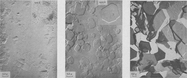
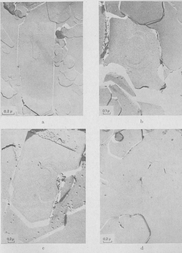
The following growth patterns were distinguished on {001} faces: These spirals are intimately connected with polytypism: Verma (1951, 1952,1953); Frank (1951a). Table 1 plots frequencies of growth features observed, against run durations. During the first stages of growth (t1 = 10 minutes, t2 = 1 hour), {001} faces are smooth, with occasionally one or two growth steps (Fig. la). Approximately polygonal islands are seen on the smallest crystallites (inset Fig. la) ; the growth of {001} faces proceeds by a secondary nucleation mechanism. For three day-experiments (Fig. 1b), exposed ledges were observed for the first time (inset Fig. 1b). In 15- and 30-day experiments, spirals are common on basal faces (Fig. 1c, 10, and 18).
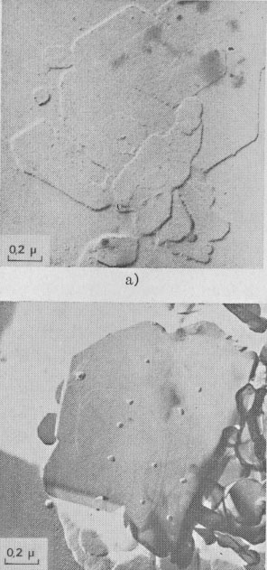
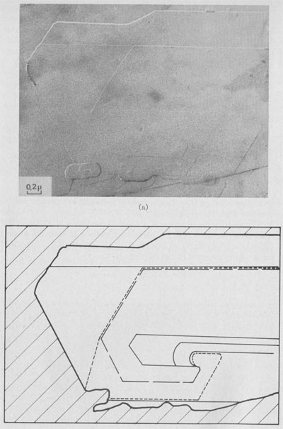
GROWTH SPIRAL ANALYSIS Among the 30 different runs of 15 days made, the great majority exhibited only type A and B spirals: they are called type I runs. Type I Runs: 1M [0] Polytype Morphology and symmetry of growth fronts. The two most frequent shapes are
shown in Figures 2a and 2c. The simultaneous observation of the crystal
morphology allows the indexing of the rectilinear parts of growth fronts,
as (a) in Figure 2a, two spirals of opposite sign with pseudohexagonal
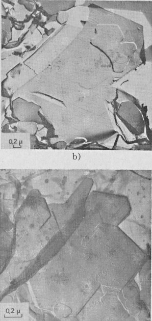
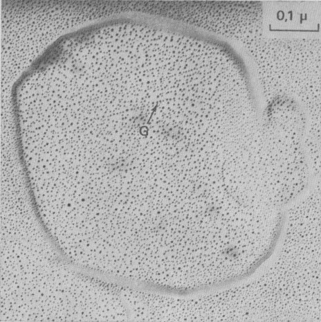
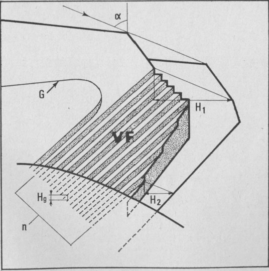
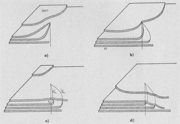
fronts, [100], [1 Growth spiral and growth pattern forms are not always closely connected with those of crystal edges bounding {001} faces (Figure 2a, b, c, d) as described for apatite by Amelinckx (1952b) and for other compounds by Brandstätter (1952, 1953). On a given crystal, the morphology of the successive fronts of a spiral originating from a dislocation group (Fig. 2b, c, d) doesn't depend on their respective height. Spiral polygonisation. A study (Baronnet) of the time variation of supersaturation near the crystals shows that it is a decreasing function of run duration; the degree of polygonisation also decreases with time [Fig. 2a (t4 = 15 days); Fig. 6a and 6b (t5 = 30 days)]. As the growth temperature is the same in all the experiments, the more or less polygonised nature of spirals may be related to variations of supersaturation and consequent changes in the critical nucleus size. Measurements of spiral step heights. Measurements of growth step heights and of the c* component of Burgers vector b(bar) of a spiral is possible for a small number of microtopographic configurations (See Figs. 3 and 4). A vicinal face created by equally spaced steps on (001) appears on a crystal laying flat on the glass slide. A part of the step G to be measured also belongs to the vicinal face: then, the mean height of the close spaced steps (h)m0 can be calculated:
H1 - H2 where: H1 and H2 are two shadow lengths measured along the gold vapor beam
direction,
Hollow dislocations in phlogopite. At the point of emergence of screw dislocations of multiple strength on {001}, empty tubes are commonly observed if the Burgers vector exceeds a critical value of approximately 20-40Å In good agreement with Frank's work (195b), the diameter D of the tube is an increasing function of b(bar) (see Figs. 6a and 6b). In Figures 2b, 8, 9, 10, and 15 other hollow cores appear. They certainly play an important part in the trapping of crystalline impurities during the growth of mica crystals. Interactions of growth
spirals. Hydroxyl-bearing phologopite exhibits classic interaction patterns previously seen on other compounds (Verma,
1953; Dekeyser and Amelinckx, 1955), such as: Burgers vector of the ith among the j edge dislocations created by the "old" spiral, then we have: i=j
This is the energetically more acceptable mechanism explaining the formation of frequent edge-dislocations seen on vicinal faces; in Figure 9 two edge dislocations of opposite sign with 20 and 10 Å Burgers vectors are visible by gold decoration.
b. Two screw dislocations of opposite hand linked by component steps
c. Cooperating spirals of the same hand; a large step links the two
d. Numerous spirals on the same crystal: the arrow shows a screw
dislocation
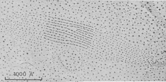
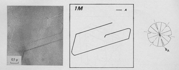
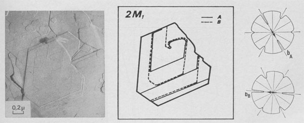
Type II Runs: Mixture of Polytypes. Among 15 days experiments, three of them exhibit interlaced spirals. Interlaced spirals with only one kind of polar diagram. The great majority of spirals with large b show very different stacking sequences of layers from one crystallite to another (Fig. 10). If b is small, interlaced or non-interlaced growth spirals corresponding to the simplest polytypic structures are observed: -In Figure 11 a single lamella is emerging on (001). The form of the growth front does not depend on its height and, therefore, the corresponding polar diagram has been drawn. It corresponds to the plane symmetry 2 and the slowest growing front is always [100]. If we assume that the P layers of the lamella are in the same orientation and if we use the Ramsdell notation followed by a Ross-Takeda-Wones Symbol (1966) to describe the successive "interlayer stacking angles" (Smith and Yoder, 1956) of the polytype, we obtain the structure 1M[0]P= 1M[0]. -In Figure 12 two lamellae A and B are distinguished, and the two associated polar diagrams are successively derived from a 120°- or 300°- rotation. As only k 120° stacking angles, with k = 0, 1, or 2, occur in the stacking sequences of natural phlogopite polytypes (Ross, Takeda, and Wones, 1966), the chosen rotation angle between A and B will be 120° and between B and A, 240°. If there are P monolayers in the lamella A, and Q layers in the lamella B, then the polytype will be:
(P + Q)M[(0)P-12(0)Q-1
(P + Q)Tc[(0)P-12(0)Q-1 -In Figure 12, P (Approximately equal) Q =1 or 2, and the spiral growth pattern can be
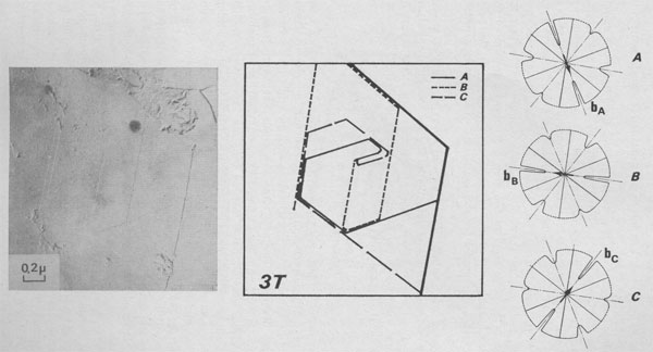
considered as the 2M1[2 -In Figure 13 three lamellae A, B, and C composed of P, Q, and R monolayers are generating a periodic succession of stacking angles: (P - 1) X 0°; 120°; (Q - 1) X 0°; 120°; (R - 1) 0°; 120°. Therefore, the stacking sequence of the polytype is [(0)P-1 2(0)Q-1 2(0)R-1 2] If P = Q = R = 1, this interlaced spiral is the growth pattern of the 3T [222] polytype.
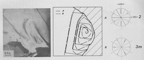
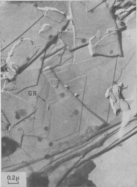
Interlaced spirals with two kinds of polar diagrams. Such spirals are the combination of two polar diagrams of 2 and 3m plane symmetries (Fig. 14). If we consider that, (a) the growth conditions are the same for the two fronts, (b) The minimum growth unit in mica is a single sheet of Cm symmetry, (c) Splitting of a spiral growth front occurs if its sequence contains interlayer stacking angles different from 0°, and that the above observations indicate that neither the height nor the orientation of the growth front with respect to the substrate has any significant influence on the shape of the polar diagram, then the reasons for the appearance of this pattern remain unknown. Interlaced spiral interactions. Figure 15 shows the complex growth patterns occurring with the interaction of several interlaced spirals on a area of one square micron. Notice that when two fronts laying on the same substrate meet others, a residual step (GR) is often observed, revealing their different heights.
DISCUSSION These detailed observations concerning surface features of basal planes of synthetic phlogopite were carried out in order to discuss the relation between growth mechanism and the origin of the various polytypes of micas. The first ideas along this line were stated by Amelinckx (1952), Amelinckx and Dekeyser (1953), and Smith and Yoder (1956). On one hand, starting from our experiments, nothing can be said about the role of composition and P-T growth conditions of crystals, these factors being maintained constant. On the other hand, the role of growth mechanisms is directly observed. Surface topographies of micas were previously investigated by means of phase contrast and interferometric microscopes by Tolansky (1946a, 1946b) who was working on cleavages, and later by Amelinckx and Dekeyser (1953). Helicoidal surfaces were recognized on muscovite and the first observation of an interlaced growth spiral on a biotite crystal was analysed in great detail and correlated with the polytypism of this mineral. Further investigations on natural crystals showed (Sunagawa, 1964) or did not show (Kretz, 1966) growth spirals; and these authors considered that mica grows either by a spiral growth mechanism or by secondary nucleation of each additional layer. Our investigations make clear that in the first case secondary nucleation is operative before the first screw dislocation appears on the crystallite.
According to Dekeyser and Amelinckx's ideas, secondary nucleation provides completely random stacking, " ... There is no reason for a secondary nucleus to adopt a selected orientation on the substrate, the stacking energy differences between the six possible ways of stacking two layers being negligible or zero . . .". If such be the case, the more common 1M [0] polytype of phlogopite can only be derived from spirals, the exposed ledges of which do not contain any interlayer stacking angle different from 0°. The simultaneous realization of these restrictive conditions, including both the stacking sequence in the exposed ledge end dislocations of very feeble strengths on numerous crystals, I consider suspicious. Smith and Yoder, based on qualitative end semiquantitative evidence, considered that order in layer stacking may also result from growth by secondary nucleation if a "structural control" between successive sheets exists. The strength of this structural control may depend on environmental conditions of growth leading to more or less ordered structures. This later view is fully supported by our investigations. In type I experiments, we observe on all crystals that whatever the strength of the first dislocation, no interlaced spirals occur, i.e., the structure of the platelet was previously of 1M[0] type. Thus the structure of the crystal as a whole will remain unchanged after the adoption of Frank's growth mechanism. We can say that the same structure was obtained by Yoder and Eugster (1954) during their study of the phlogopite stability range under similar P-T conditions. They did not succeed in distinguishing between 1M[0] end 3T[222] polymorphs, the two X-ray powder patterns being identical.
In type II runs, various strengths of dislocations end emerging stacking
sequences are contributing to give very different growth patterns on
{001}, and consequently different surface structures. As no correlation
between interlayer stacking angle distributions is observed on the
different crystals grown under the same conditions, we deduce that their
adopted basic structure was disordered, i.e., 1Mrn(120),
and consequently
their initial growth occurs by secondary nucleation. Among the randomly
distributed 0°, 120°, 240° stacking angles, we notice that 0° is the
more common. If screw dislocations with small b appear on this basic
structure, short period types like 1M[0], 2M1[2
Simultaneous activity of several uncooperating spirals will induce, in the
more general case, a "patch-work" of different polytypic domains
in syntactic coalescence, which may be bounded by fault surfaces. As the
supersaturation decreases, a certain part of the above spirals will become
cooperative giving a common polytypic structure if core distances d <
2πρc, with ρc as the radius of the critical nucleus for the considered
supersaturation. The consequence of such a change will lead once more to a
superposition of polytypes. While it is clear that the above
considerations are supported by our observations, it does not follow that
the growth of each mica crystal is always so complex. In spite of the
common occurrence of spiral growth features on (001) faces, we consider
that polytypism and especially the appearance of short period polytypes in
micas are chiefly governed by secondary nucleation mechanisms. Further
work in the line of this paper is required to establish if 2M1[2 ACKNOWLEDGMENTS The writer is particularly grateful to Professor R. Kern, in whose department this work was done, for his encouragement during the course of this study and for the critical discussion of this manuscript. Thanks are also due to Mr. R. B. Roy for helping with the translation of this paper. REFERENCES AMELINCKX, S. (1952a) La croissance helicoidale de cristaux de biotite. C. R. Acad. Sci. Paris. 234, 971-973. _________ (1952b) Spiral growth patterns on apatite crystals. Nature, 169, 841-842. (1952c) Growth spirals and their relation to crystal habit as illustrated by apatite. Nature, 170, 760-761. ________, AND W. DEKEYSER (1953) Le polytypisme des minéraux micacès et argileux. C. R. XIXth Congr. Geol. Int. 9-22; [Mineral. Abstr. 12, 520]. BASSETT, G. (1958) A new technique for decoration of cleavage and slip steps on ionic crystal surfaces. Phil. Mag. 3, 1042-1025. BRANDSTÄTTER, M. (1952) Spiralen und Schichtenwachstum an Kristallen aus der Dampfphase I. Mitteilung. Z. Elektroch. 56, 968-972. _______ (1953) Spiralen wachstum an Kristallen aus der Dampfphase II. Mitteilung. Z. Elektroch. 57, 438-444. DEKEYSER, W., AND S. AMELINCKX (1955) Les Dislocations et la Croissance des Cristaux. Masson et Cie Paris. FRANK, F. C. (1951a) The growth of carborandum: Dislocations and polytypism. Phil. Mag. 42, 1014-1021. ________ (1951b) Capillary equilibria of dislocated crystals. Acta. Crystallogr. 4, 497-501. GRITSAENKO, G. S., AND N. D. SAMOTOYIN (1966) The decoration method applied to the study of clay minerals. Proc. Int. Clay Conf., Jerusalem, Israel, 3, 391-400. KRETZ, R. (1966) Growth of phlogopite crystals in marble from Quebec. I.M.A. Pap. Proc. Fifth Gen. Meet.-Cambridge, England, p. 85-93. ROSS, M., H. TAKEDA, AND D. R. WONES (1966) Mica polytypes: Systematic description and identification. Science, 151, 191-193. ROY, R. (1956) Aids in hydrothermal experimentation: II. Methods of making mixtures for both "dry" and "wet" phase equilibrium studies. J. Amer. Ceram. Soc. 39, 145-146. SELLA, C., P. CONJEAUD, AND J. TRILLAT (1960) Nouvelle méthode d'étude par microscopic électronique de la structure superificielle des faces de clivages d'halogénures alcalins. IV Int. Kongr. Elektronenmikrosk. 1, 508-512. SMITH, J. V., AND H. S. YODER (1956) Experimental and theoretical studies of the mica polymorphs. Mineral. May. 31, 209-231. SUNAGAWA, I. (1964) Growth spirals on phlogopite crystals. Amer. Mineral. 49, 1427-1434. TAKEDA, H. (1971) Distribution of mica polytypes among space groups. Amer. Mineral. 56, 1042-1056. TOLANSKY, S. (1946a) Interferometric studies on mica. Phil. Mag. 37, 453-462. ________ (1946b) Further interferometric studies with mica. Proc. Roy. Soc. London., Ser. A. 186, 261-271. TUTTLE, D. F. (1949) Two pressure vessels for silicate-water systems. Geol. Soc. Amer. Bull. 60, 1727-1729. VERMA, A. R. (1951) Observations on carborundum of growth spirals originating from screw dislocations. Phil. Mag. 42, 1005-1013. _______ (1952) Further observations of growth patterns on silicon carbide (Si-C) crystals. Phil. Mag. 43, 441-446. ________ (1953) Crystal Growth and Dislocations. Butterworths Sci. Publ., London. YODER, H. S., AND H. P. EUGSTER (1954) Phlogopite synthesis and stability range. Geochim. Cosmochim. Acta. 6, 157-185. Manuscript received, January 26, 1972; accepted for publication, April 5, 1972.
| ||||||||||||||||||||||||||||||||||||||||||||||||||||||||