| Home | AmMin | GMR | RiMG | Collectors Corner | Directory | Short Courses | |
|
|
|||||||

|
|
Volume 24, pages 661-676, 1939 VARIATION OF HARDNESS IN THE DIAMOND1
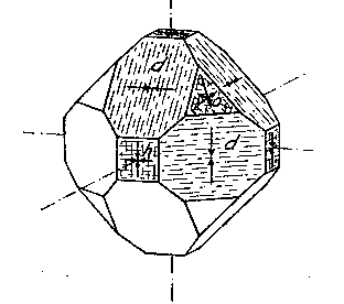
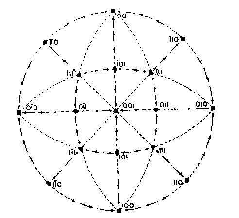
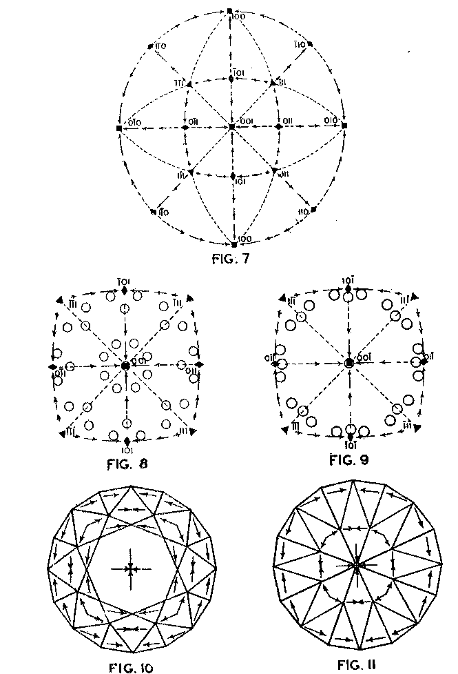
EDWARD H. KRAUS AND CHESTER B. SLAWSON, INTRODUCTION It has long been known that hardness is a vector property. For many substances hardness curves have been determined showing that this property varies with the different crystal faces of the substance and also with the direction on the faces. That the hardness of the diamond varies materially in this manner has been common knowledge to diamond cutters. Unfortunately erroneous statements concerning the variation of the hardness of the diamond have found their way into mineralogical literature, and only in recent years have efforts been made to correct these statements. Significant contributions to our knowledge of the hardness of the diamond and its relation to crystal structure and to cutting for gem and industrial purposes have been made by W. Fr. Eppler, H. Rose, K. Schlossmacher, and more recently by H. Bergheimer. It is the purpose of this paper to discuss the variation of the hardness in the diamond, as established by the experience of diamond cutters, in terms of crystallographic theory, crystal structure, valence bonds, cleavage, and growth and solution phenomena. VARIATION OF HARDNESS WITH THE CRYSTAL FACE In the sixth edition of Dana's System of Mineralogy, 2 published in 1892, the hardness of the diamond is given, as is customary, as 10. However, there is also the statement that the hardness is greater on the faces of the cube than on those of the octahedron, but without reference to the source or the basis for the statement. Similar statements were subsequently made by M. Bauer,3 G. Tschermak,4 F. Zirkel,5 H. Miers,6 C. Hintze,7 A. Sauer,8 and others.In 1925 Eppler and Rose 9 called attention to the fact that experience showed that the statements commonly found in mineralogical texts are incorrect and that the octahedron faces of the diamond are materially harder than those of the cube. They also indicated that the faces of the rhombic dodecahedron have an intermediate hardness. In spite of these published observations statements have continued to be made in some texts10 that the cube faces are the hardest.Both Eppler 11 and Schlossmacher12 have discussed at length the variation of the hardness in relation to diamond cutting and confirmed the earlier statements by Eppler and Rose. They also pointed out that diamond cutters have long known that the hardness is greatest on faces of the octahedron, and that it varies materially with direction. The optimum directions for cutting or grinding, commonly designated as polishing, as given by them are those which are parallel to a crystallographic axis. Similar statements have been made by Bergheimer.13 Accordingly, the following generalizations may be made:(1) Since faces of the cube h (Fig. 1) are parallel to two crystallographic axes, there are two optimum polishing directions on each of these faces. Facets parallel to these faces are the easiest to polish. (2) Faces of the rhombic dodecahedron d are parallel to one crystallographic axis. Consequently each face has one optimum direction, which is parallel to the short diagonal of the face. (3) Since octahedron faces o are equally inclined to the three crystallographic axes, these faces show the greatest possible divergence from parallelism with the axes. They are accordingly the most difficult to polish. Indeed, it is impossible to make any progress on such faces or on planes exactly parallel to them. 14CRYSTALLOGRAPHIC THEORY The stereographic projection showing the faces of the cube {001}, rhombic dodecahedron {101}, and octahedron {111} (Fig. 2), may be used to indicate the transition in hardness from one face to another in terms of the above statements, and also to give the optimum directions.
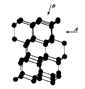
The variation in hardness is approximately indicated by the length of the arrows; that is, the longer the arrow the more readily the polishing takes place. Hence, the hardness of the planes with the longest arrows is less in the directions indicated than on other planes or in other directions. In other words, it is evident that the change in hardness from one face or from one direction to another is not abrupt but gradual. This is in accord with the observations on the variation of hardness in other substances, and the behavior of vector properties in general. The projection also shows that the sense of direction is of much importance, as for example, on octahedron faces where polishing must always be in directions perpendicular to and toward the edges of the face. These are the directions that tend to approximate parallelism to a crystallographic axis. It must be borne in mind, however, that to make progress, even in these favorable directions, the plane must not be exactly parallel to the octahedron face, but be somewhat inclined to it. The dashed lines in the projection indicate directions in which no progress in polishing can be made with diamond dust. CRYSTAL STRUCTURE The foregoing observations can be shown to be in full accord with the crystal structure of the diamond which has been accurately determined by the Braggs and intensively studied by others. A careful study of a model which gives the spatial arrangement of the carbon atoms in the diamond (Fig. 3) and their distribution in various planes, reveals the following facts: (1) In the direction of the crystallographic axes A the atoms are uniformly and widely separated (Figs. 4 and 5). (2) As the atoms are uniformly spaced in these directions, hardness is, hence, bivector in character. There is no sense of direction (Fig. 1). (3) No valence bonds lie in these directions. (4) The crystallographic axes intersect valence bonds at larger angles than do any other directions through the structure.
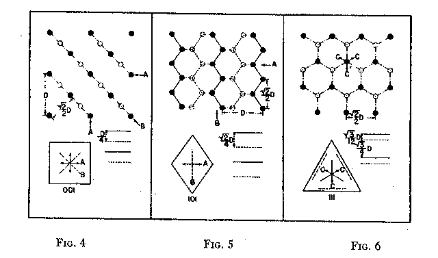
FIG. 4. Diagrams showing (a) distribution of atoms in cube planes, (b) spacing of successive parallel planes, (c) optimum directions for polishing and sawing A, and (d) directions of greatest resistance B. FIG. 5. Same for rhombic dodecahedron planes. FIG. 6. Same for octahedron planes. The three optimum polishing directions are indicated by C. These facts indicate that in the direction of the three crystallographic axes the forces holding the structure together can be most readily overcome. This is in full accord with the experience of diamond cutters, already referred to, namely, that the optimum directions for polishing are parallel to the crystallographic axes A (Fig. 4). Moreover, the distribution of the atoms in planes parallel to two crystallographic axes, that is, in the planes of the cube (Fig. 4) is such that the reticular density is less than in rhombic dodecahedral (Fig. 5) or octahedral (Fig. 6) planes. Accordingly, the faces of the cube are the easiest to polish. This fact has also been long known to diamond cutters. It is therefore obvious why it is advantageous to cut diamonds so that the table is parallel to a face of the cube. In the diamond cutting industry, diamonds cut in this manner are known as four-point stones. In the diagonal directions B in the cube planes (Fig. 4) the distribution of the atoms is closer than in the direction of the crystallographic axes A. Moreover, it is such that the spacing of them in successive planes is staggered. These directions should hence offer much resistance to polishing, which is in accord with experience. In the stereographic projection (Fig. 2) these directions (B) are dashed to indicate their extreme hardness. As has already been pointed out, octahedral planes are equally inclined to the three crystallographic axes, and accordingly show the greatest possible divergence from parallelism with them. The distribution of atoms in these planes shows an hexagonal pattern with close spacing. The arrangement of successive planes is such that they are alternately closely and widely separated (Fig. 6). The closely separated planes are so close together that the atoms in them are sometimes considered as forming "puckered" carbon rings. 15Each atom of these puckered rings (Fig. 3) has three of its valence bonds in these closely arranged planes while the fourth bond is perpendicular to the planes. In addition the reticular density of the atoms is greater in the octahedral planes than in any other. Thus, the atoms in these closely separated planes are held most firmly together while the bonds between successive pairs of such planes are weak and readily ruptured. In this way the superior hardness of the octahedral planes can be explained as also the fact that, due to the wide separation of successive pairs of planes, cleavage takes place easily parallel to them. Figure 3 shows this structure and the direction of two of the cleavages, A and B. As shown in Fig. 6 the arrangement of the atoms in these closely arranged pairs of planes is such that the sense of direction is important. The direction of polishing should be perpendicular to the intersection of two adjacent octahedral faces, or in other words in directions that approach the short diagonals of the rhombic dodecahedron. As has already been pointed out, these diagonals are parallel to a crystallographic axis. The opposite direction is unfavorable because it is toward and approaches the diagonal of the cube face, which is very resistive. The favorable direction may also be indicated as the one that bisects two adjacent valence bonds between atoms in successively closely spaced planes, directions C (Fig. 6). To determine these directions the diamond cutter makes use of the so-called grain indicated by the growth lines which are parallel to the intersections of octahedral faces (Fig. 1). It must be again emphasized that even in these more favorable directions no progress in polishing can be made if the facet is exactly parallel to the octahedral plane. To make progress the facet must be somewhat inclined away from the octahedron plane, and obviously the more it is inclined; the more it will approximate a face of the rhombic dodecahedron. Diamonds which are cut with the table approximately parallel to an octahedral plane are called three-point stones. Faces of the rhombic dodecahedron are parallel to one crystallographic axis and intersect the other two axes at equal angles. Accordingly, one direction, that of the short diagonal of the face, is most favorable for polishing. The direction of the long diagonal shows the greatest possible divergence from parallelism with an axis, and hence offers extreme resistance to polishing. These observations are also in accord with the arrangement of the atoms in the rhombic dodecahedron plane (Fig. 5). Each atom has two valence bonds in the plane, that is, they are co-planar. In the direction A, that of the short diagonal, the atoms are widely spaced and the valence bonds make large angles with this direction. The A direction is favorable for polishing. The direction of the long diagonal B; in which the atoms are more closely spaced and the co-planar bonds are intersected at small angles, is unfavorable. Diamonds cut with the table parallel to a face of the rhombic dodecahedron are called two-point stones. From the above considerations it is obvious that the rhombic dodecahedral planes are intermediate between those of the cube and octahedron with respect to the facility with which they may be polished, those of the cube being the easiest and those of the octahedron the most difficult. VALENCE BONDS It may well be assumed that the ease or difficulty of cleavage- parallel to different planes, the variation in hardness, and the effects of solution upon a crystal are largely determined by the forces or valence bonds which hold the atoms in their structural positions. As the crystal structure of the diamond is well known it is possible to calculate approximately the valence bonds for unit areas and thus determine their relation to cleavage, hardness, and solution effects. Cleavage The comparative ease or difficulty with which cleavage can take place parallel to certain planes may be determined by calculating the forces or valence bonds per atom which exist between unit areas of successive parallel layers of atoms. That this can be done for the diamond has already been pointed out by Ewald, 16 Mohr17 and Bergheimer.18 Cube planes are uniformly separated one from another and each atom in these planes has two valence bonds which extend to atoms in the next successive parallel layer. Rhombic dodecahedral planes are also uniformly separated, but each atom has only one such valence bond between successive layers. In the case of octahedron planes the successive layers are not uniformly separated, but are alternately widely and closely arranged. In the case of the widely separated planes there is only one such valence bond, while for those planes that are closer together there are three bonds which must be taken into consideration. Professor Kasimir Fajans has very kindly calculated the relative number of bonds per atom for unit areas (D2) for successive parallel layers of atoms for the above-mentioned four types of planes. His results are as follows:D 2Octahedron (wide) 4/3/¯3 = 1 Rhombic dodecahedron 2/¯2 = 1.22 Cube 4 = 1.73 Octahedron (close) 4/¯3 = 3 It is thus evidence that cleavage should take place readily parallel to the octahedron and also that there is a possible cleavage parallel to the rhombic dodecahedron of which some diamond cutters, especially Mr. Lazare Kaplan, make practical use. These values obtained by Fajans agree with those given by Mohr. The value 1.22 calculated by Fajans and Mohr for the rhombic dodecahedron differs from that obtained by Ewald, namely, 1.53, but the relative order of the various planes is the same. Mohr has already called attention to this difference in the published values for the rhombic dodecahedron. Hardness As indicated by Bergheimer, 19 the values obtained above for cleavage cannot be used to estimate the relative hardness per unit area on the different crystal surfaces. To do this it would seem necessary that the valence bonds per atom which lie in the plane must also be taken into consideration. In the case of the cube and octahedron planes there are no additional bonds to be considered. However, each atom in a dodecahedral plane has two bonds lying in that plane (Fig. 5) which are equivalent to one additional effective bond. When this fact is taken into consideration the following relationship is obtained:Cube
4 = 1 These values would indicate that experience and theory are well in agreement, namely, that the hardness should be greatest on the octahedron, least on the cube, and intermediate on the rhombic dodecahedron. Solution effects When a solution acts upon a crystal, the atoms in the layer attacked are removed individually. The relative ease or difficulty with which the different crystal planes may yield to solution can be approximately determined by calculating the number of atoms per unit area, and of the bonds between the atoms in the plane itself, and of those connecting them with the atoms in the next succeeding layer. This calculation leads to ratios that are identical with those obtained for hardness, namely.
Accordingly, from the standpoint of structural relations it appears that solution should take place most easily upon faces of the cube and most slowly upon those of the octahedron, and that the rhombic dodecahedron planes occupy an intermediate position. These conclusions are in full accord with the observations of Fersmann and Goldschmidt. 20OPTIMUM DIRECTIONS ON FACETS In the various public presentations of this paper (Footnote 1) it was shown by lantern slides, that since the various facets may be considered as crystal planes, the stereographic projection (Fig. 7) maybe used to indicate their location and also the optimum directions on them for polishing. Figure 8 is a projection of the crown or upper part of a four-pointed brilliant cut diamond, where a cube face (001) is the table. This method has also been used by Bergheimer in a recently published paper. 21The basis of Fig. 8 is the projection as given in Fig. 7, which shows the transition in hardness from one face to another. The various facets of the crown are located upon this projection and the optimum directions for polishing are readily determined from the basic projection. The relative ease or difficulty of polishing the various facets can be estimated from the lengths of the arrows on the adjacent zones through the cube, rhombic dodecahedron, or octahedron. The location of the facets upon the projection will obviously depend upon the fundamental angles used in cutting the diamond. Practice in this regard varies somewhat.22 The positions given in Fig. 8 and in subsequent figures are based upon the calculations of Tolkowsky,23 and represent fairly accurately the usual American practice. A comparison of these figures with those of Eppler and Kluppelberg, and Bergheimer will accordingly show some slight differences both as to position and optimum cutting direction.
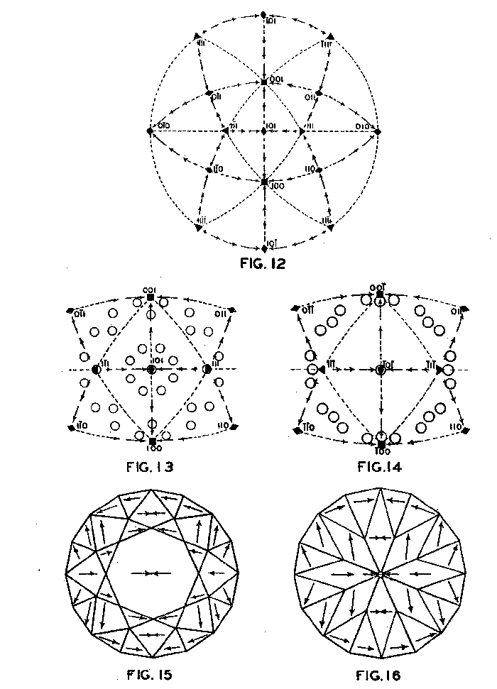
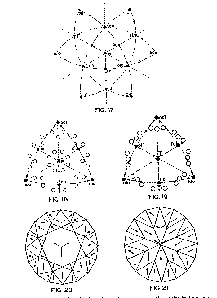
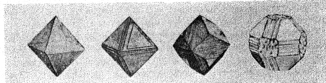
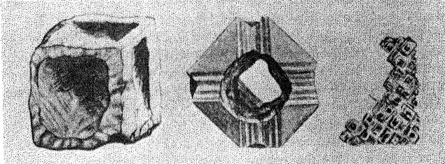
Figure 9 shows the projection of the pavilion, or back, of a four-point stone. To make these relationships clearer arrows showing optimum polishing directions and ease of cutting may be placed upon a projection of a facetted stone. Figures 10 and 11 give these conditions for the crown and pavilion of a four-point stone. Similar projections have been used by Bauer, 24 Eppler25 and Bergheimer.26 Figures 12-16 and 17-21 are corresponding projections for two-point and three-point stones, respectively.GROWTH AND SOLUTION PHENOMENA In 1911 A. von Fersmann and V. Goldschmidt 27 published the results of their exhaustive study of the growth and solution phenomena to be observed on the fundamental crystal faces of the diamond, namely, on the octahedron, rhombic dodecahedron, and cube. These studies were made before the development of x-ray analysis for the determination of crystal structure. Accordingly, it is our purpose to discuss briefly some of their observations and conclusions in terms of crystal structure and valence bonds.Fersmann and Goldschmidt made the fundamental assumption that the principal or main faces or planes of growth are those in which the attractive forces are the greatest, while the principal faces or planes of solution are those in which the attractive forces are the weakest. Their observations were made on a large number of crystals of diamonds from various localities and led them to postulate that (1) the octahedron is the main growth face, that is, these faces tend to develop more rapidly than the others; (2) the main solution face is that of the cube, that is, these faces are most readily attacked by solvents; and (3) faces of the rhombic dodecahedron occupy a somewhat intermediate position. Figures 22, 23, and 24 taken from the Atlases 28 of Fersmann and Goldschmidt indicate different stages in the growth of octahedral faces. These figures also show the manner of development of the growth lines or grain,29 upon which the diamond cutter places so much reliance for the proper orientation of the crystal. FIG. 22. Diamond octahedron. FIGS. 23 and 24. Diamond crystals showing the development of growth lines or grain. FIG. 25. Diamond crystal showing the effect of solution on the faces of the cube. FIGS. 26 and 27. Diamond crystals showing marked effects of solution on faces of the cube. FIG. 28. Characteristic solution effects on cube face (greatly enlarged). According to Fersmann and Goldschmidt, Fig. 25 30 shows the effects of both growth and solution phenomena. The octahedron faces are growth forms, while the action of solution is evident on the faces of the cube. That solution may cause deep depressions, and even holes, on the cube faces is shown by Figs. 2631 and 27.32 Moreover, the effect of solution is such that characteristic outlines or figures are often formed on the cube face. These are evident in Figs. 26 and 28.33 These designs were interpreted by them to be the result of the probable joint action of solution and growth. For it is stated that "the principal solution current attacks the crystal at right angles to the cube face and flows away over the rhombic dodecahedron." Also that "if the mother liquor is strongly solvent, the current will continue to cause solution, but if it is only slightly solvent it may become neutral during its course, and finally lead to deposition and growth. Consequently, it may occur that while solution takes place on the cube face, particles may be deposited on the octahedron."34Thus, the central portion of each design, Fig. 28, is said to be caused by solution, while the outline or ridges are assumed to be the result of growth. It is also pointed out by them that these ridges are in the zone of the cube and octahedron. In other words, the directions of these ridges indicate intersections of octahedral planes with those of the cube. In view of the earlier discussions under crystal structure and valence bonds it is suggested that there may be another explanation for these interesting outlines on the faces of the cube. These outlines must not be confused with growth lines or grain. Since these ridges may be assumed as the intersections of octahedral and cube planes, it seems quite logical to assume that the ridges are the result of the greater resistance to solution of the closely spaced atoms and the greater strength of the valence bonds in the octahedral planes, rather than that solution and growth take place simultaneously in areas of such extremely small dimensions, such as those in Fig. 28, which are greatly magnified. It appears much more plausible to assume that, due to the manner in which the atoms are arranged and bound together, certain portions of the crystal face can be dissolved more readily than others. It may, moreover, be pointed out again that the crystallographic axes, which are perpendicular to the cube faces, are the directions in which the atoms are widely spaced and the valence bonds weak. Accordingly, it is suggested that these outlines on the cube faces may well be interpreted as the result of differential solution. DIAMOND DUST The question is often asked why is it possible to saw, grind, or polish the diamond with its own dust. In the light of the foregoing discussion a very definite explanation is possible. Diamond dust is prepared by crushing a crystal or fragment to fine powder. In the crushing process, due to the excellent octahedral cleavage, small particles with cleavage surfaces result. By following well established procedures, dust of uniform grain size may be obtained. Usually several kinds of dust are prepared which vary from coarse to fine depending upon the size of the particles. The sawing of a diamond is done by means of a small, thin, phosphor-bronze disc which revolves rapidly. The edge of the disc is impregnated with diamond dust and oil. For polishing purposes a horizontally revolving cast-iron plate or wheel called the "skeif" is used. The skeif is somewhat porous. When diamond dust mixed with olive oil is placed upon it, the particles lodge or embed themselves in the pores or pits. In the random distribution of the dust in the saw or skeif, some of the particles will obviously have cleavage surfaces exposed. Since these are the hardest surfaces, such particles are able to abrade the stone in directions of inferior hardness, that is, in those not parallel to the octahedron faces, and most readily in those parallel to a crystallographic axis. As the particles are loosely held they are free to turn or roll and hence new portions will be exposed. Then, too, the fine particles which are removed from the stone during the process assist in the sawing and polishing. 35Sawing is best accomplished in directions parallel to the faces of the cube, commonly called the sawing grain. Experience shows that it is almost impossible to saw the diamond if the plane of the cut varies more than a few degrees from that of a cube face. Although there are possible sawing grains parallel to the faces of the rhombic dodecahedron, they are not commonly used. ACKNOWLEDGMENTS We are indebted to Messrs. Lazare and Leo Kaplan of New York City, and Mr. J. Levy of Detroit for information and helpful suggestions on diamond cutting; and to Professor Kasimir Fajans of the Department of Chemistry of the University of Michigan for advice and assistance in the calculation of the valence bonds.
NOTES 1 A large part of the material of this article was presented in abstract form, or in considerable detail, illustrated with lantern slides showing many of the figures, at the following meetings:
December 28, 1938, The Mineralogical Society of America, New York City. At each of these meetings a discussion followed the reading of the paper. 2 P. 4.
3 (a) Lehrbuch der Mineralogie, Second Edition, 244 (1904). 4 Lehrbuch der Mineralogie, Sixth Edition, 383 (1905). 5 Naumann-Zirkel, Lehrbuch der Mineralogie, Tenth Edition, 402 (1898). 6 Mineralogy, 294 (1902). 7 Handbuch der Mineralogie, 5 (1904). 8 Mineralkunde, 123 (1905). 9 Einige Beobachtungen am Diamant, Centralbl. Mineral., Geol., and Pal., 251-253 (1925).
10 Williams, A. F., Genesis of the Diamond, Vol. II, 465 (1932).
11 (a) Der Diamant and seine Bearbeitung (1933). 12 Bauer's Edelsteinkunde, Third Edition (1932). 13 Die Schleifharte des Diamanten and seine Struktur: Neues Jahrb. fuer Mineral., Geol., and Pal., 74, 318--332 (1938). 14 Compare E. H. Kraus, and C. B. Slawson, Gems and Gem Materials, Third Edition, 98 (1939). 15 Clark, G. L., Applied X-Rays, Second Edition, 308 (1932). 16 Annalen der Physik, 44, 281 (1914). 17 Abhandhing, Heidelberger Akademie der Wissenschaft, Math-Nat. Klasse, Abteilung A, 12 Abhd., 34 (1924). 18 Reference 13, p. 330. 19 Reference 13, p. 330. 20 Reference 27, Text, XI. 21 Bergheimer, H., Die Schleifrichtungen auf den Facetten des Diamantbrillianten; Neues Jahrb. fuer Mineral., Geol., and Pal., 75, 145-158 (1939).
22
Reference 14, pp. 83-85. 23 Tolkowsky, L., Diamond Design, London (1919). 24 Edelsteinkunde, First Edition, 277 (1896). 25 Reference 11a, pp. 126-152. 26 Reference 21, pp. 152-153. 27 Der Diamant, Text and Atlas (1911). 28 Plate 5, crystals 2, 5, and 4. 29 See p. 666. 30 Atlas, Plate 17, crystal 50. 31 Ibid., Plate 23, crystal 69. 32 Ibid., Plate 17, crystal 49 33 Ibid., Plate 23, crystal 61. 34 Text, p. 220.
35 Reference 12, p. 62.
|