Variation of F and Cl X-ray intensity due to anisotropic diffusion and
electron microprobe analysis of apatite: An addendum
John C. Stormer, Jr. and Milton L. Pierson
Department of Geology & Geophysics MS-126
Rice University, 6100 South Main St., Houston, TX 77007, U.S.A.
(jstor@rice.edu, miltonp@rice.edu)
Introduction
Stormer, et al. (1993) documented anisotropic variability in halogen x-ray intensity during electron microprobe analysis which is large enough to produce a significant problem for precise analysis. This work was done on sections perpendicular and parallel to the c axis. In the discussion of Stormer, et al. (1993) it was assumed that the effect at other angles could be represented by a uniaxial ellipsoid of a 20:1 aspect ratio. This suggested that the effect might be negligible for sections cut within 20° of the c axis. We now have obtained data on sections cut at a variety of angles which shows that Stormer, et al. (1993 ) underestimated the severity of the effect.
Results
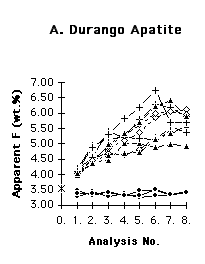
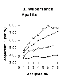
Figure 1. shows the effect of the anisotropic diffusion on apatite for typical analysis conditions which give reasonable count rates. Clearly, these conditions will give apparent fluorine contents which are significantly in error unless the grain is oriented with the c-axis nearly parallel to the surface of the section. Reducing voltage aggravates the problem by producing a shallower depth of electron deposition and a steeper electrical field gradient. Reducing current lowers the slopes seen in figure 1, but also lowers count rate and precision. The use of a W-Si multilayer pseudocrystal (rather than TAP) is necessary since it completely suppresses the third order phosphorus K-alpha interference, and gives a count rate more than an order of magnitude higher. (See Stormer, et. al.,1993 for details.)
Fig. 1. Apparent fluorine content in sequential replicate analyses of the same spot on variously oriented sections of Durango and Wilberforce apatite standards. Independent accepted values for fluorine content shown by cross on y-axes. All analyses done with 15 kV accelerating voltage, 10 nA beam current, 5 µm diameter spot, counting 20 s. on both peak and background. A. Durango Apatite, 3.53 wt.% F; section with c axis parallel to surface
X; c perpendicular to section D; c 46° from perpendicular A ; c 23° from perpendicular H. B. Wilberforce Apatite, 3.75 wt.% F; four grains of unknown orientation. Both sets of data show a tendency to extrapolate toward the accepted value of fluorine content at time zero(I). The Durango apatite data show that the effect described by Stormer, et al. (1993) is strong even for grains which are oriented with the c-axis as far as 46° from the perpendicular. Both sets of data show that grains with the c-axis nearly parallel with the section can be identified with sequential analysis and will yield the most reliable results.Discussion
The procedure that we now use for analysis in our laboratory (Cameca SX-50 with Quantiview software) is to use 15 keV accelerating voltage, 10 nA current, and a spot >5 µm. With four spectrometers set on F, Cl, Ca, and P, each point is analyzed under exactly the same conditions five times without moving the stage. Analyses for other elements are run after collecting the five sequential points since other elements vary slowly. The exact routine for collecting the data will depend on the microprobe software in use. However, it is essential to collect a timed sequence of F and Cl analyses on the same point with minimum time of beam exposure. The fluorine and chlorine data can be extrapolated to time zero to obtain an estimate of the fluorine and chlorine contents. Grains with the steepest and most irregular slopes on such a plot may need to be discarded from the data set.
We are continuing to explore other possibilities for optimizing the analysis. The extrapolations are now done by eye after plotting the data. Simple linear extrapolation is not adequate since the data define a curve. Alternatives for automatic extrapolation algorithms are being examined. The use of voltages higher than 15 keV could possibly be advantageous. Although not normally recommended for routine analysis of minerals such as apatite, higher accelerating voltages by extending the electron penetration depth might lower the electrical gradient within the apatite which drives this phenomenon. It is also possible that this phenomenon is influenced by the thickness of the carbon coating, or other surface preparation. Further experimentation along these lines may be fruitful.
Reference cited
Stormer, J. C., Jr., M. L. Pierson, and R. C. Tacker (1993) Variation of F and Cl X-ray intensity due to anisotropic diffusion in apatite during electron microprobe analysis. American Mineralogist, 78, 641-648.